Accelerated Life Cycle Comparison of Millenniata Archival DVD Page One |
|
Prepared By: contents | page one | page two | page three Final Report for Millenniata DVD Testing SUMMARY The test that was performed met the intent of the specifications set forth in the original plan; however, the irradiance levels during light exposure could have been controlled better. It is believed that the results are valid. None of the Millenniata media suffered any data degradation at all. Every other brand tested showed large increases in data errors after the stress period. Many of the discs were so damaged that they could not be recognized as DVDs by the disc analyzer. 1. INTRODUCTION In October 2009, the Life Cycle and Environmental Engineering Branch of the Naval Air Warfare Center Weapons Division at China Lake conducted an accelerated life cycle test of archival DVDs from Millenniata Incorporated. The test compared archival discs from Millenniata and competitors by observing the increase in read errors due to combined temperature, humidity, and light conditions. This test was carried out in accordance with the Archival Optical Media Test Plan supplied by Millenniata (1). This report will cover the test in four sections. The first section, the introduction, will set forth some definitions used in the body of the report as well as give a brief overview of the Millenniata test plan. The test preparation and execution section which follows will describe the instrumentation, setup and execution of the test. Test results, including the test environment and its impact on the discs, will be presented in the results section. Lastly, the meaning of the results and recommendations springing from the test will be stated in the conclusion. Data not presented in the results section will be included in the appendices. 1.1 DEFINITIONS 1.2 MILLENNIATA TEST PARAMETERS The two key elements of the Millenniata test which differ from ECMA-379 are consideration of the initial write quality of the discs selected for testing, and the introduction of full spectrum light to the test environment. 1.2.1 DISC CREATION AND ANALYSIS In the test plan, a write-drive selection process is called for. Drives from at least 3 different manufacturers must be tested with media of every dye-based brand used. The drive which provides the best write quality for each manufacturer is used to burn all discs for that manufacturer. Discs used in the test are required to be less than 12 months old and obtained directly from the manufacturer or through known distribution channels. A minimum write speed of 4X must be used to write a 4.2 to 4.3 gigabyte image on each disc. Before testing, a visual inspection and read analysis must be performed on all discs. Those exhibiting visible imperfections or a PI8 Max Error rate above 175 were excluded from the test in order to ensure that only discs of acceptable write quality were used. Under the specified test protocol, data analysis is not required to cover the entire disc; three test bands or regions are required. The protocol defines an inner band starting at a 25mm radius, a middle band at 40mm and an outer band at 55mm in order to reduce analysis time. A minimum of 2,400 ECC blocks are to be read from each band and re- read 5 times. The same 2,400 ECC blocks are to be read in each succeeding analysis. 1.2.2 TEST CONDITIONS
The conditions specified during the 24 hour dwell period are listed below in Table 1-1.
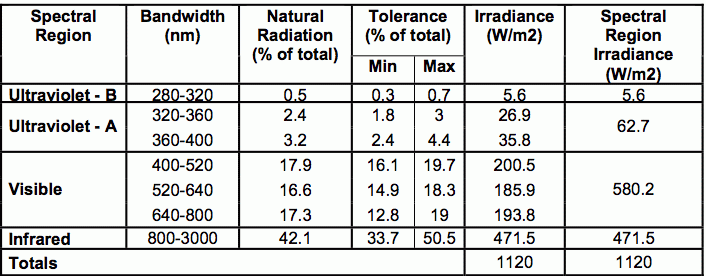
The light used in the test is further defined by spectral power distribution guidelines. Military standard 810G and the spectral power distribution Table 505.5-I therein is referred to for irradiance levels. This table is shown below.
2. TEST PREPARATION AND EXECUTION <2.1 TEST INSTRUMENTATION 2.1.1 DISC MEASUREMENT
For disc analysis two ShuttlePlex playability analyzers from Worthtech (3) were used. These units are not complete disc analysis systems but high-grade consumer technology-based analyzers. They are not meant for use as complete analysis systems to provide data in reference to a Standard. Instead, they are used to provide relative playability information. As a result, readings such as PI8 Max are not identical for different reads of the same ECC blocks. This was mitigated during the test by repeating all disc measurements 5 times and averaging the result. 2.1.2 CHAMBER MEASUREMENT
Self-adhesive type T thermocouples which meet the ANSI special limits specification were used to measure disc temperatures within the chamber. The insulation temperature range and ANSI special limit tolerances for these thermocouples are listed in Table 2-3.
Irradiance information was collected with a CMP3 pyranometer manufactured by Kipp & Zonen B.V. This pyranometer was selected for cost and usability at elevated temperatures. The capabilities of the CMP3 are shown in Table 2-4.
The output voltage of the CMP3 was read and converted to W/m2 by an Omega DP41-B universal input meter. This meter was then used to output a 1 Volt per 1000 W/m2 signal to a National Instruments NI cDAQ-9172 chassis with a NI 9234 module. This NI 9234 module was also used to record the output from the humidity sensor. In addition to the NI 9234 module a NI 9213 module was used to measure the thermocouple outputs. The NI cDAQ-9172 chassis was linked to a computer running LabView Signal Express 3.0. A program was made for Signal Express which recorded temperature, humidity and irradiance values every 10 seconds. For each reading 500 samples were taken at a rate of 1 kHz and then averaged to obtain the measurement for that 10-second interval. 2.2 DISC PREPARATION 2.2.1 DRIVE CHARACTERIZATION
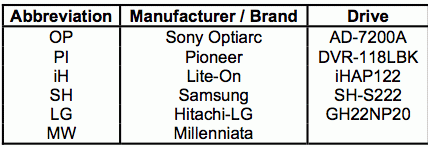
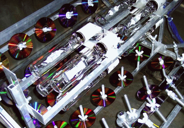
The drives were connected to the ShuttlePlex units using USB to IDE adapters. This method of using the drives proved troublesome. In all configurations, the Hitachi-LG drives were not recognized and could not be used in the test. The other drives also exhibited issues with disc recognition throughout the characterization process. This was solved by the addition of a line conditioning uninterruptible power supply and did not create problems during any subsequent writing and analysis. For characterization purposes, a single drive from each manufacturer was used to burn three discs from each media manufacturer. The written discs were then analyzed and the average PI8 Max value for each disc manufacturer was graphed for each drive. One or more drives were then selected for each media based on the lowest PI8 Max average. The Sony drive was determined to be best for Mitsubishi and Verbatim, Lite- On and Sony were chosen for MAM-A, and Pioneer was chosen for Delkin and Taiyo Yuden. After determining which drive performed best with each media brand, three discs of each media brand were burned using the remaining drives from the selected manufacturer in order to evaluate performance variation between same-brand drives. This exercise demonstrated that all drives from the same manufacturer do not perform equally and cannot be used interchangeably. Thus, only the top performing drive, or drives, from each manufacturer were selected for use in this analysis. (In one instance, that of the Pioneer drives, two drives performed similarly, and therefore qualified for interchangeable use.) This exercise was conducted to ensure the best write quality for each dye-based disc brand. Again, this was done because not all drives from the same manufacturer performed equally and, therefore, could not be used interchangeably. 2.2.2 DISC CREATION AND ANALYSIS To provide a comparison to current media, every archival DVD currently on the market and a high quality non-archival DVD was tested alongside the Millenniata media. The six brands tested are listed below in Table 2-6. A sample size of 25 discs from each manufacturer was decided upon to balance statistical significance with test time. To account for defective discs, substantial quantities of each brand were bought. Discs from each manufacturer were burned on their matching drive and then analyzed. To save time, a full disc analysis was not performed on the discs. Instead, a 2,400 ECC block sample was repeated 5 times at an inner radius of 25mm, a middle radius of 40mm and an outer radius of 55mm. Discs which exhibited a PI8 max below 175 were admitted to the disc sample and those failing to meet this requirement were thrown away. Four elements were instrumental in obtaining accurate results during this analysis. First, the ShuttlePlex units were warmed up before the start of each analysis session by running some non-test discs through an analysis. Second, the ShuttlePlex was programmed to perform the disc sampling and repetition without ejecting the sample disc. Thirdly, at intervals throughout the test, discs with known error levels were run through an analysis to check that the machines did not drift during the test. The data from these correlation runs was used to correlate the ShuttlePlex units back to a calibrated Pulstec ODU-1000. Lastly, the analyzers were powered by a line conditioning uninterruptible power supply to prevent reading differences cause by voltage fluctuations. 2.3 CHAMBER SETUP AND CHARACTERIZATION 2.3.1 EXPOSURE FIXTURE To carry out the Millenniata test plan, a fixture was required to hold the discs and lights. This rig required corrosion resistance, adaptability and efficient utilization of chamber volume. The assembly fabricated to meet this need was designed for use in a Thermotron SE- 1200L. The SE-1200L was found to have insufficient cooling and humidity generation capability for the test, so the fixture was modified for use in a Sexton Espec altitude chamber which had been retrofitted with a Thermotron 8800 controller. The assembly as it sits in the Sexton Espec chamber is shown in Figure 2-1.
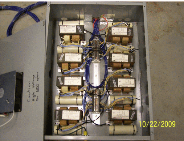
This rig uses eight lamps to produce 3.2kW of light and expose 50 DVDs to irradiance levels in the range of direct sunlight (1120 W/m2). The setup is composed of four main sections: a ballast box, a light array, an upper rack and a lower rack. The ballast box holds eight ballasts which conform to the ANSI H33 specification for 400W mercury lamp ballasts. The ballasts used in the box have taps for 120V, 208V, 240V and 277V. The box is wired for 208V and is limited to use on a minimum 20amp circuit. In addition to a 208V connection the box requires a 120V connection to power the fan. The fan is very important, as the transformers inside the box dissipate close to 700W of heat during operation. The interior of the box is shown in Figure 2-2.
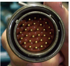
The ballast box is located outside of the chamber and is connected to the lamp array by a 10 foot long wiring harness with a multi-pin connector. This connector, shown in Figure 2-3, fits in the pass through holes on the chamber allowing easy placement and removal of the light array.
The lamp array which the wiring harness connects to is 36” long and roughly 8” square. It holds eight Clean AceTM MT400DL/BH metal halide lamps from Eye Lighting International of North America, Inc. These lamps provide light that is very similar to natural sunlight with a color rendering index of 90 and a corresponding color temperature of 6500K. This array, as Figure 2-1 shows, is mounted horizontally between the two racks. It is supported by the lower rack and is adjustable in the vertical axis to allow positioning equidistant from the upper and lower racks. A more detailed view of the light bar is shown in Figure 2-4.
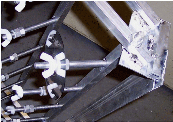
This photograph shows the front cluster of four bulbs. There is a front and rear set, both of which can be moved independently along the central axis of the setup. This allows the radiation pattern to be adjusted for uniformity along the depth of the racks. Each rack is composed of a frame and 7 disc rows. The rows are arranged around the lamp array in an arc with a 20” radius. Each row is 36” long and has 6 rods spaced equally along the length. So that the discs can be pointed at the light source, each row is free to pivot around its long axis. To maintain the desired angle, the rows are secured by tightening a nut at each end. Figure 2-5 shows this pivot point and securing nut.
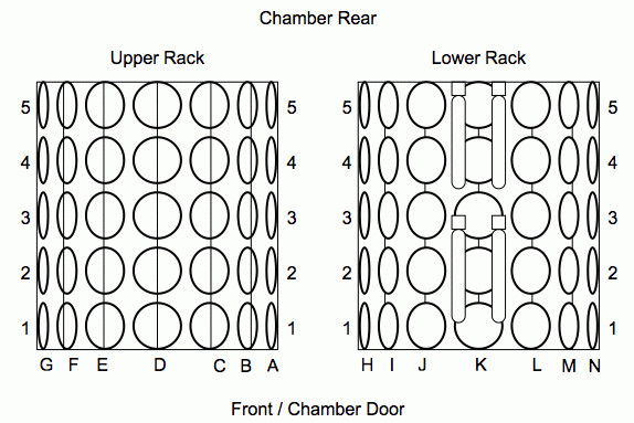
In addition to the pivoting point, Figure 2-5 also gives a good view of the rods used to hold discs. These rods are 6” long sections of threaded 1⁄2” aluminum. On each rod there are two aluminum nuts which are free to travel along the rod. This travel controls the irradiance at each location and is locked by tightening the nuts against each other. A nylon washer prevents the nuts from scratching test discs while a nylon wing nut clamps the discs down. The final adjustment mechanism in the rig is the method of holding the rig in the chamber. As can be seen in Figure 2-1, both racks are suspended in the chamber by brackets on the side of the chamber. Because the racks are separate, they can be moved closer or farther apart to adjust light levels. The racks include a numbering system. Figure 2-6 depicts the fixture as it would appear looking through the chamber door showing the alphabetic row designation used. The upper 7 rows are labeled A through G and the lower 7 rows are labeled H through N in counterclockwise order. The row designation is accompanied by a numeric depth starting with number 1 located in front next to the door and ending with the last usable location, number 5, at the rear of the chamber. This is illustrated in Figure 2-7 which shows a bird’s eye view of the rack numbering.
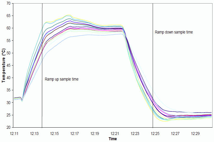
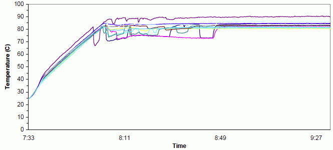
This location numbering system was used throughout the test to record disc positions. 2.3.2 PROTECTIVE MEASURES In addition to the electrocution hazard posed by the fixture, the light itself was a danger. Because the lamps used in this test were chosen for their representation of sunlight they are not filtered for ultraviolet radiation. Consequently, at the irradiance levels encountered while adjusting the fixture, sunburns and eye damage were a major concern. Due to the warm up and cool down periods inherent to metal halide lamps it was necessary to run the lights with the chamber open during all adjustments. This posed a danger for both those adjusting the fixture and bystanders. To protect uninvolved people, spectra welding curtains which block the dangerous wavelengths below 500nm were set up around the chamber door and the viewing window of the chamber was covered. For the operator head to toe covering was required. A welding helmet with a #10 shade was used to shield the eyes and face. Underneath the welding helmet a nomex hood was worn to protect the neck and uncovered portions of the head from light and heat. For protection of the arms and torso, in addition to a long sleeve shirt, a multilayer jacket was donned. The jacket had cuffs which could be tightened over the wrist to improve maneuverability as well as preventing entrance of light. These cuffs were tightened over sheepskin gloves with extra long gauntlets. The close fitting sheepskin was necessary for dexterity during the irradiance adjustment process. In addition to the gloves and other protective gear long pants were worn with leather shoes. 2.3.3 IRRADIANCE ADJUSTMENT Once this preliminary adjustment was completed the individual rows were all rotated to point at the center of the lamp array and tightened down enough to prevent movement during further adjustment and the test itself. The lights were then turned on and irradiance measurements taken to determine if the radiation pattern was reasonably consistent from the front to the back of the chamber. This was not the case and the lights were de-energized to move the two bulb clusters farther apart and closer to the front of the chamber. After adjustment proper irradiance levels were attainable from the door to depth 5. With the major adjustments finished the chamber was ready for adjustment and recording of light levels at every disc location. To do this, the chamber was filled with a representative sample of discs and the lights were allowed to burn at room temperature for over an hour. The irradiance at each position was then adjusted by moving the aluminum nuts and taking a reading. When the reading appeared to be close to the desired irradiance, the chamber door was shut and the irradiance recorded. After every location was measured, the lights were extinguished and the nuts were tightened against each other to lock in the adjustments. This process was performed on all 70 usable locations and took two people a day to complete. 2.3.4 TEMPERATURE ADJUSTMENT Initially, disc temperatures within the chamber varied by more than 10°C. To remedy this various scoops and baffles were tested. Because full temperature tests with lights would have taken over 2 hours, they were not a viable option for trying new arrangements. Instead, as a first check, an anemometer was used to measure airspeeds in various areas. Once an arrangement was deemed to be worth testing further, the chamber was quickly ramped up to 60°C and back down as shown in Figure 2-8.
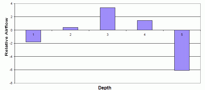
This quick temperature ramp was useful because thermocouple equipped discs positioned in locations that had greater airflow responded to the chamber conditions quicker than other discs. To make use of this, two sets of thermocouple readings were taken, one at the end of ramp-up and one at the end of ramp-down. The average value for the ramp-up condition was then subtracted from every ramp-up reading and the average ramp-down temperature was subtracted from the ramp-down values. This ramp-down difference was then subtracted from the ramp up difference to give a total ramp difference. The total ramp difference was then graphed on bar charts such as Figure 2-9 to demonstrate which portions of the chamber had excessive or insufficient airflow.
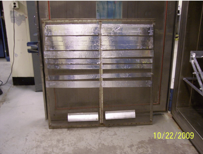
When these graphs exhibited a significant improvement over previous attempts, the chamber was run up to temperature with lights and humidity to check the actual temperatures. The end result of this tweaking process was two scoops located on the chamber fan screen 3½” from the rear and a large amount of aluminum tape on the end nearest the door. Figure 2-10 below shows the fan screen as it was used in the test.
After 2 ½ days of airflow adjustment, this combination was judged to be the most effective solution with a temperature spread in the 5°C range. This range may have been improved marginally by further testing, but it was felt that the results were reasonable for this test and the effort would be better spent elsewhere. During the initial testing to determine if the chamber could maintain temperature and humidity with the light rig, it was found that the disc temperatures were significantly higher than the chamber air. This was compensated for by adjusting the chamber set point during the airflow modification. The set point that was arrived at by the end of airflow testing was 77.5°C. The final step in preparing the chamber with regards to temperature was mapping the disc locations for hot and cold spots. Ideally, this would have been performed by running the chamber one time with thermocouple discs in every location. Only ten discs with thermocouples were available however, so the chamber was characterized over multiple runs. Because the temperature runs were lengthy, readings were taken at every other location and the missing readings were interpolated from surrounding data. The results of the temperature characterization revealed an issue with the chamber setup. The temperatures varied more than was indicated by the disc placement used to adjust the airflow in the chamber. As a result, many locations were over the limit or on the high side of the allowable range. It was observed that if the temperatures were universally lower the number of spots falling within tolerance would be improved. The chamber set temperature was therefore lowered 2°C to 75.5°C. Instead of performing the temperature mapping again with the new set temperature, the chamber was run up twice to gather readings at the new set point. These readings were then compared to the previous readings to determine an adjustment value for the temperature map. In addition to temperature differences within the chamber, there was a temperature difference between the Millenniata discs and the dye based media. This temperature difference was anticipated so, during the temperature mapping process, Millenniata discs with thermocouples were placed in locations that were recorded with a normal disc during other temperature mapping runs. The difference between the conventional disc temperatures and the Millenniata temperatures was then used in conjunction with the temperature map to place Millenniata discs in locations that would allow similar temperatures. 2.3.5 TEST CYCLE ADJUSTMENT
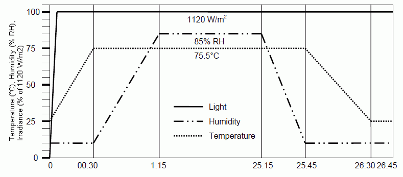
To alleviate this condensation issue, the ramp up profile was changed from the initial 30 minute temperature ramp and 30 minute humidity ramp to a 30 minute temperature ramp with a 45 minute humidity ramp. In addition to modifying the ramp up program, the ramp down was changed as well. For the ramp down though, the humidity stage was left at 30 minutes and the temperature ramp was extended to 45 minutes. This was done to aid the de-humidification function of the chamber and avoid a large increase in relative humidity due to quickly cooling the air in the temperature ramp down. These modifications to the ramp profile greatly decreased water spotting and completely eliminated reading fluctuations due to condensation. The final program that resulted from the modifications was 26 hours and 45 minutes long. This program is recorded in Table 2-7 and depicted graphically in Figure 2-12.
After checking with Millenniata this stress cycle was used for all three test runs. 2.3.6 DISC LOADING AND UNLOADING For each run, an equal number of discs from each manufacturer were placed in a random order on the racks. The one exception to this was the Millenniata discs. They were placed in previously decided locations with lower temperatures that compensated for the higher running temperatures of the Millenniata media. A thermocouple equipped Millenniata disc was also located in proximity to Millenniata test discs for actual temperature verification during the three runs. To make sure the location of each disc was recorded correctly, the disc location was recorded when putting the discs in as well as taking the discs out. 2.4 POST STRESS DISC MEASUREMENT The same steps performed during the disc creation process were repeated for the final analysis. Each disc was analyzed on the machine it had originally been read on. The drives were warmed up before each analysis period was started and, periodically, a calibration disc was analyzed to check that there was no drift in the readings. contents | page one | page two | page three For additional information about this product line, please visit the M-DISC™ Information Page. You may also view or download this information here. |


